Beautiful day for flying out here in the Valley today, mid-80s, calm winds, clear and a million. But I am stuck on the ground until I can get (at least most) of the pieces on the hangar floor attached to the plane. Up today is some more work on the firewall and in particular the radiator expansion bottle.
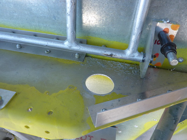
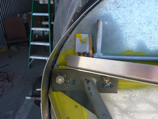
The neck of the bottle goes through the shelf on the firewall where the cap gets screwed on top and the bottom rests on a bracket. When positioning it you have to be aware of the proximity of the (hot) oil reservoir to the side, and the throttle bellcrank on the top. After fussing around a bit I came up with something that seemed to work, traced around the bottle neck under the shelf, determined a centre for the hole, made a pilot hole, eventually using the step bit to get to an inch. That still wasn’t big enough so I then kept filing it until it was.
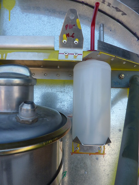
With the bottle locked in place with the cap on I marked the location of the bracket and drilled some rivet holes into it.
It was at this point that I found a place in the plans on a different page that gave measurements for the corners of the bracket so I measured mine and found I was within a couple of mms of what the plans said. Crazy.
The plans call for a 1/8″ venting hole to be drilled in the cap so I took out the #30 drill and made a hole.
Earlier in the morning I had deburred and primed all the throttle bellcrank related parts from the previous weekend so after taking care of the new parts I had everything back on the firewall ready to be riveted. I briefly considered not riveting the bottle bracket as you can’t get the bottle out with the bracket in place but I couldn’t see why I’d need to so I went ahead and riveted it. I hate leaving things unriveted!
In that picture you can see one of the throttle attaches riveted, along with accompanying doubler. I also riveted the top hole of the bellcrank brackets, the bottom hole has to be pulled from inside the cockpit so I will do that next time the top skin is off.
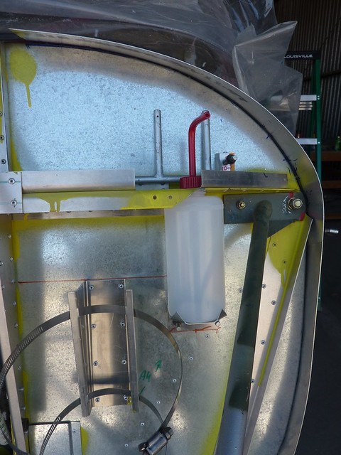
Finally here’s a picture of everything at once.
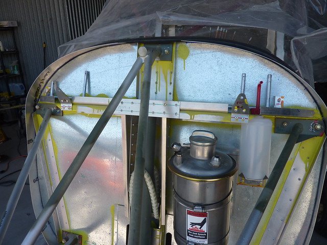
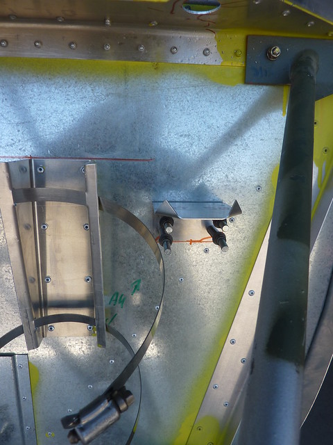
The throttle instructions have led me to needing to ask Zenith a question. In the middle of the firewall above you can see a bracket with two horizontal flanges above the shelf. The instructions say to put that on the back but everything I saw otherwise said to put it on the front so I did. The throttle plans call for a choke cable connector to go in the middle where that bracket is with two extrusions on either side.
In the video they use the flanges on that bracket to feed the choke cables through and secure the connector and that seems the obvious thing to do. They are a bit flimsy though so another thought was to put the two pieces of extrusion that are supposed to hold the cables either side of the flanges.
But the plans give a specific location for the extrusions – one would be almost in the centre of the bracket, the other a way to the left (as we look at it). So I could do that, too, but I’d have to drill holes in the flanges to let the cables go through.
I’m guessing it doesn’t matter much but not knowing about these things I want to not get it so wrong, it doesn’t work.